Lab 3: Keypad Scanner
Introduction & Learning Objectives
In Lab 3, I designed and constructed a circuit on my FPGA to read a 4-by-4 matrix keypad and display the last two hexadecimal digits pressed on dual seven-segment displays. My design satisfied all the requirements, including:- Design does not lock up when multiple buttons are pressed at once.
- Design only registers first button press if additional buttons are pressed down while holding down one button.
- Each button press registered only once (e.g., no switch bouncing)
- Seven segment displays are same brightness regardless of how many segments are illuminated.
- Design has no latches.
- Design has no tristate buffers.
- Design uses synchronizers on asynchronous inputs to mitigate metastability.
The source code for the project can be found in the associated Github repository.
Design
To quote Professor Brake, “This is a thinking person’s lab.” As such, I spent a fair amount of time designing a Finite State Machine (FSM) to read the in the matrix keypad inputs, and then creating a block diagram to understand how my modules will intersect.
Scanning FSM
The FSM to read the inputs worked by cycling through pulling each row to high, and looking to see if any of the columns were high, which was tracked in the keyPressed variable. If the FSM found that a key was pressed, it would enter a waiting stage until the button was unpressed. I handled decoding the row and colomn pairs wihtin my FSM module with my scanDecoder module. This allowed me to output the keyDecoded, keyPressed, and the rows from the scanFSM module to interact with other modules. 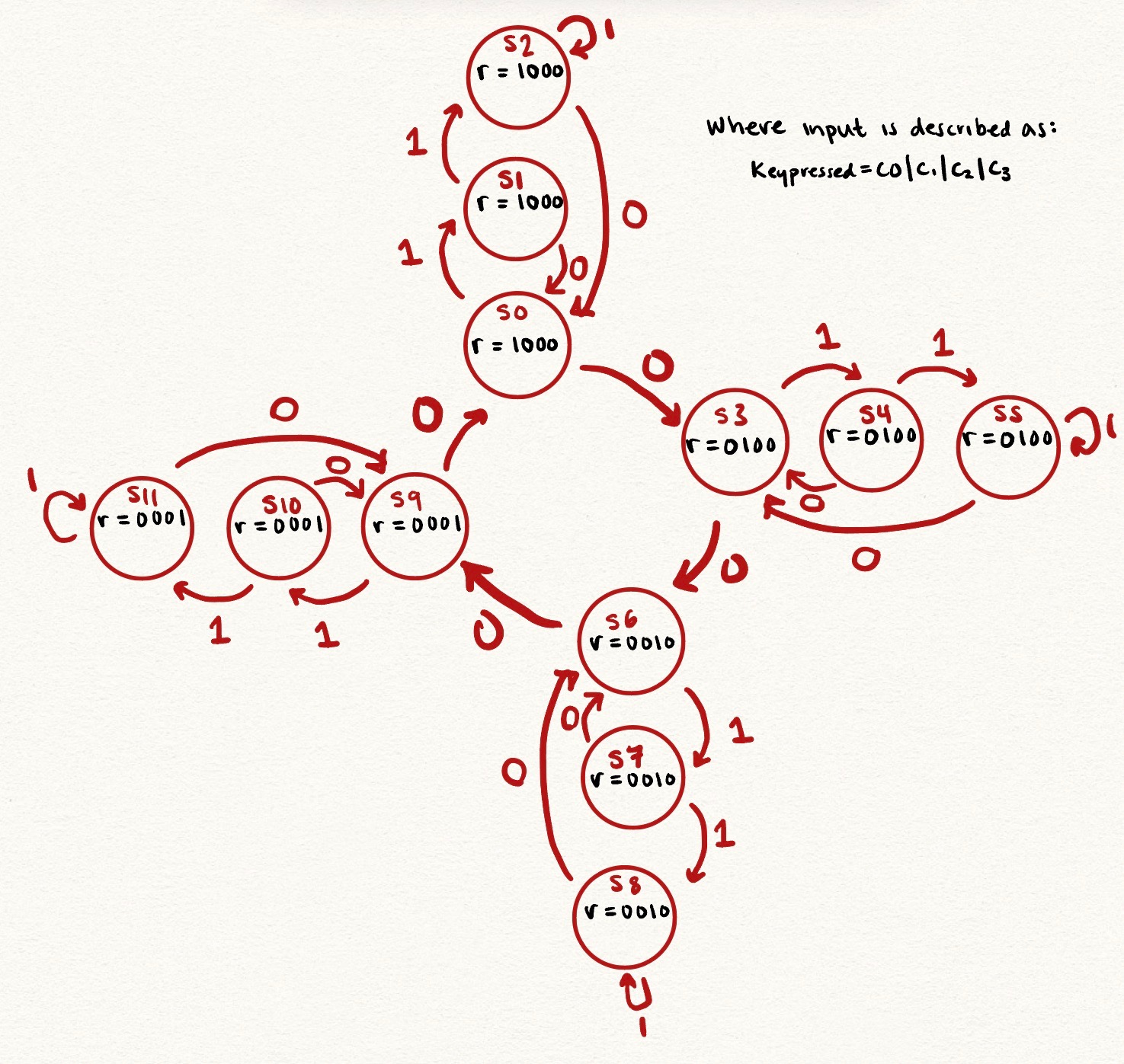
Key Debouncing FSM
I then passed through keyDecoded and keyPressed into the keyBounce module, that used an FSM to deal with key debouncing. This FSM had four states: a waiting state, a counting state, a printing state, and then a holding state. The FSM is in the waiting state until keyPressed is high. Once the key is pressed, a counter is triggered. Once the counter reaches a threshold value, then an enabled signal is activated and the signal is displayed on the seven segment display. Then the FSM enters the holding state until the button is unpressed.
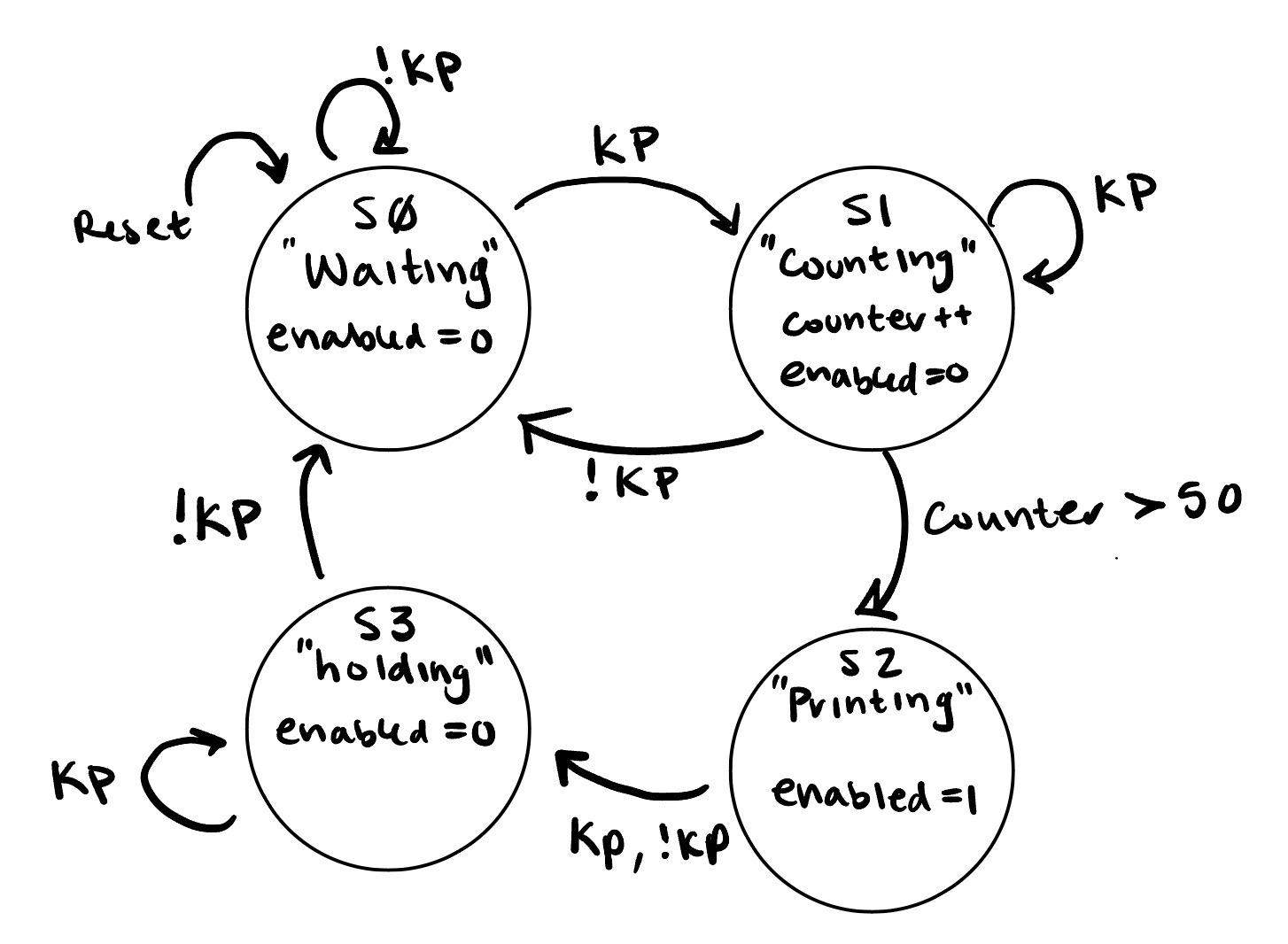
Seven Segment Display
With the keyBounce FSM, a shifter module was called to shift the display on the dual seven segment display and show the new value. The keyBounce FSM ultimately served to disregard quick, high signals.
Printing and multiplexing the seven segment display was handled with the code from Lab 2
Design Tradeoffs
My design was broken up into many different modules, with different FSMs or combinational logic being used to implement my design. I opted for this approach so that it would be easier to test smaller behaviors, and allowed me to edit functionalities without impacting other functionalities.
For example, to implement switch debouncing, I implemented a FSM with different states. At first, I attempted an approach without an FSM – using a lot of if statements. However, as the behavior got more complicated, I started to infer latches. To stop this, I opted to draw an FSM so that I can step away from “thinking like a programmer” and start thinking about the hardware.
A block diagram of my entire design is here: 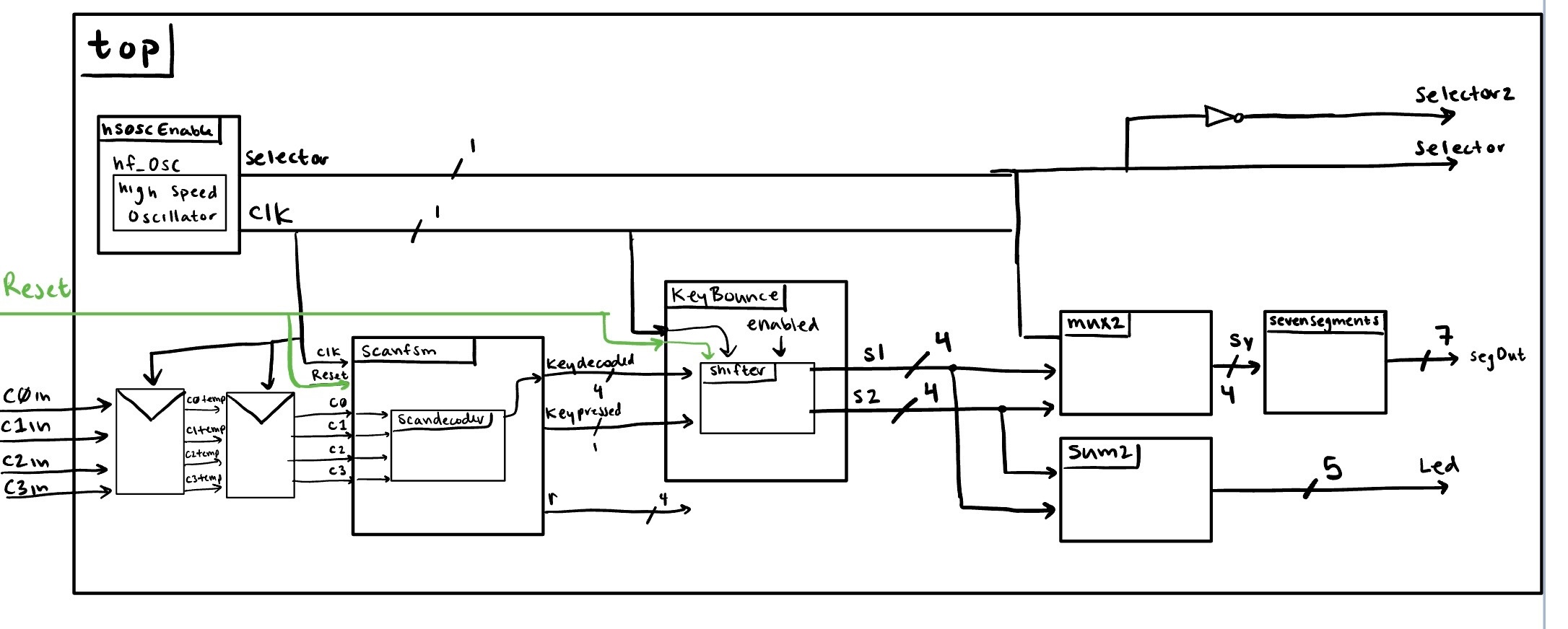
Simulation and Testing
The first step here was to test all the modules in modelSim before running on Radiant. This avoided many headaches – as I wrote test benches for each individual model to ensure expected behavior.
My waveforms for each model is below: 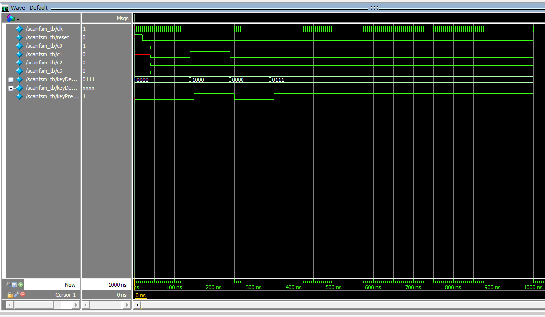
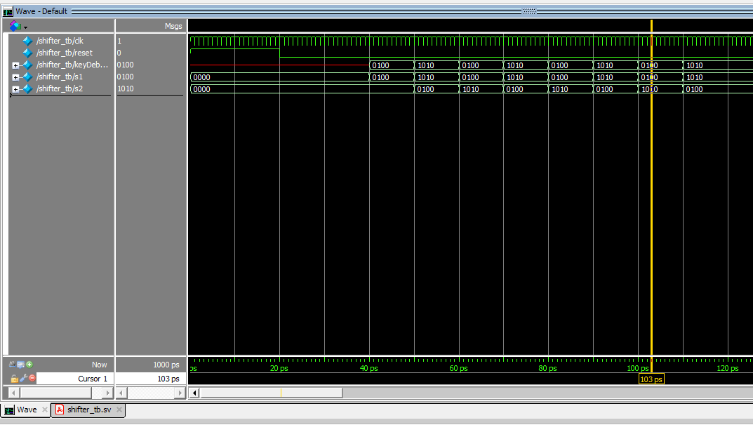
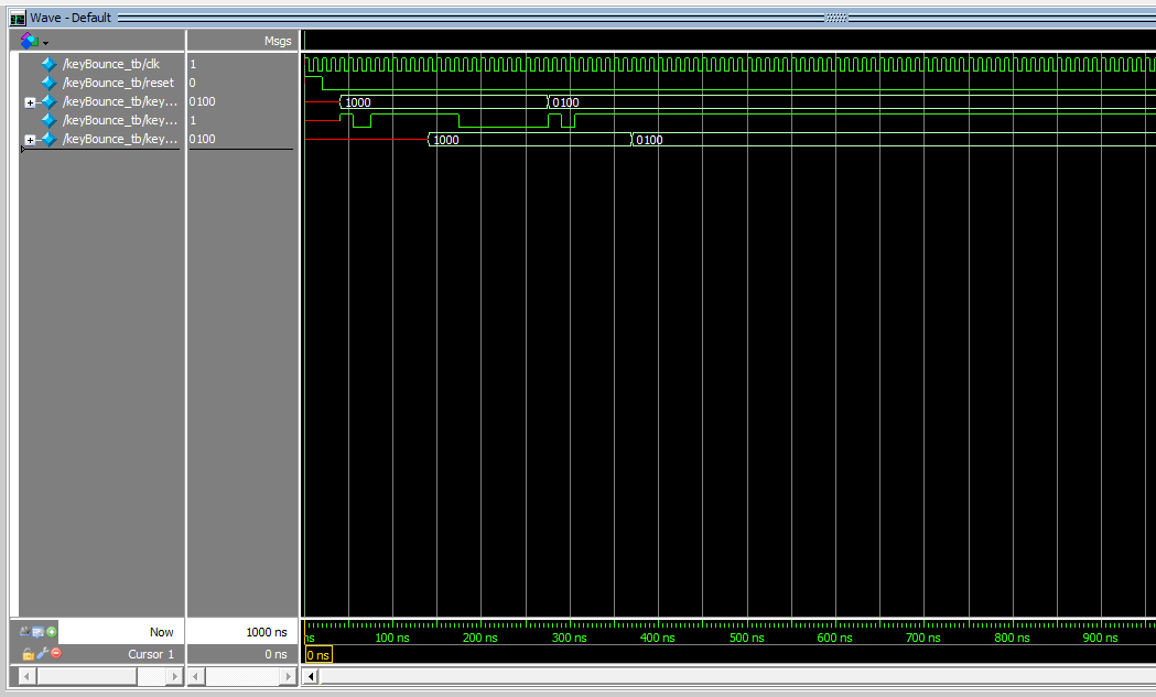
My mux, sum, and sevensegments module was taken from Lab 2, where I implemented test benches last week.
Implementation
The circuit diagram of my implementation, including pin mapping, is here: 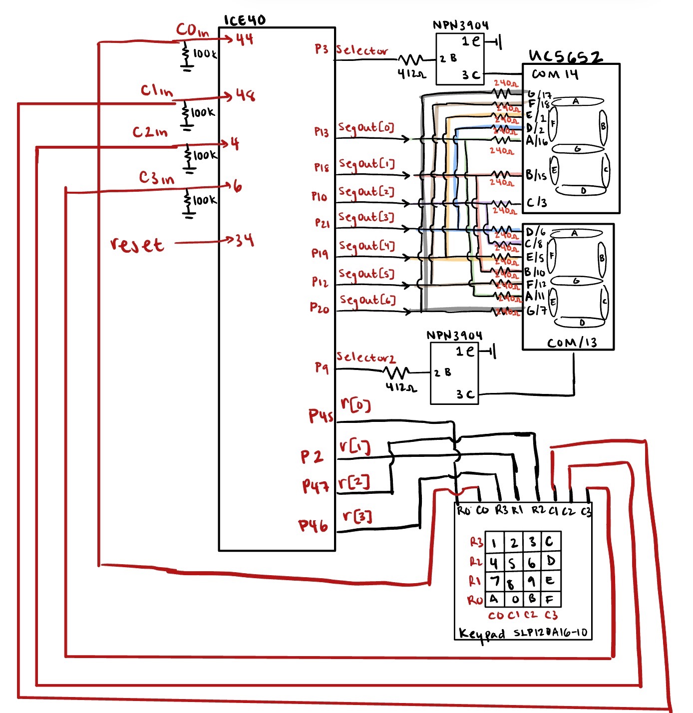
Debugging in Implementation
During the implementation of my design, I encountered a few bugs. In doing so, using the oscilloscope ot visualize which rows are high allowed me to isolate bugs in my FSM. Additionally, the oscilloscope helped me decide the threshold value for my key debouncing module.
Handling Metastability
To handle metastability, I implemented two flip flops and temporary variables to try to line the async input with the clock edge.
Conclusion
Lab 3 proved that simulation prior to implementation is a necessity. As a result, I grew familiar with fully defining my system, and how to debug.
Lab 3 meets all the requirements, and took me approximately 30 hours to complete